
3D-printed IoT lock box using ESP32
My eventual goal with electronics is to create autonomous robots and drones; I’d like to make a quadcopter with my own flight controller that can take off, land, and follow a target. This will be quite an ambitious project, and I’m nowhere near capable enough for that yet.
Previously, I created a simple plant monitor that reported stats to an online dashboard. This allowed me to learn soldering, stripboards, and 3d printing. To work on future projects, I need to be able to produce ever more complicated circuits and mechanical designs.
After watching some Lock Picking Lawyer on YouTube, I was inspired to think about different locking mechanisms. A locking box would be a good experiment with mechanical design, and if combined with IoT, would be good for electronics too.
In this article, I will cover how I created my lock box - from the problems I had, the iterations I made, and the final design I settled on. It’s a bit of a random project, I didn’t have set goals in mind. I started by exploring different locking mechanisms, and then moved to focusing on the electronics and getting it working.
Initial servo designs #
Pin #
My initial idea was to use a servo to move a pin to unlock the box. Whilst I could have used the servo head as part of the lock mechanism directly, I didn’t want the servo to be a load-bearing part of the lock.
My first design was to use a pin, a paperclip pushrod, and a two-part slot. I found it quite hard to get the pin to move straight without falling out at the end. The slightest bit of misalignment in the two latches also caused a lot of friction on the pin. Due to these problems, I decided to change to a design that didn’t need as much horizontal movement.
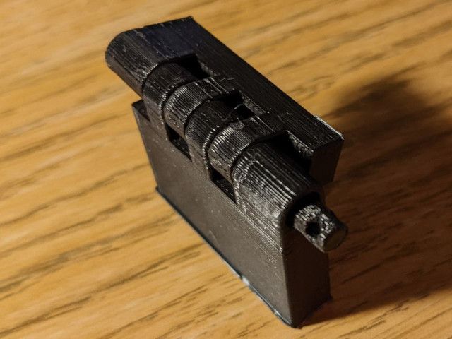
E-shaped gripper #
My second design used a servo to move an E-shaped gripper. When in the locked position, the gripper blocks the lid from being removed by colliding with tabs on the side of the lid.
The nice thing about this design is that it didn’t need much calibration, the servo just needed to be in the right place to move the gripper.
However, the servo I used was pretty unreliable - it would frequently do 360° rotations and break the lock. I also had problems with removing the lid, there was way too much flex in the lid and base, causing it to get stuck at weird angles.
Another problem is that I designed the case before the electronics, and underestimated the amount of space I’d need for them. Increasing the size of the case to fix the electronics would exacerbate the problems further, I need to come up with a design with fewer moving parts.
Solenoid design #
I had bought a cheap solenoid lock from PiHut a few months ago, so I decided to redesign the box using it. I also decided to get the full electronic design done first and then design around that, allowing the case to correctly fit the electronics.
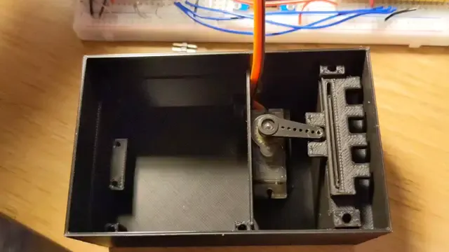
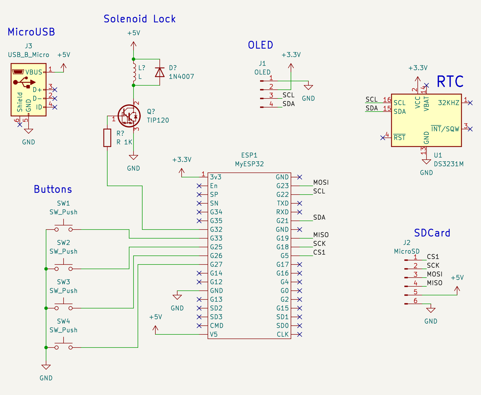
Electronics #
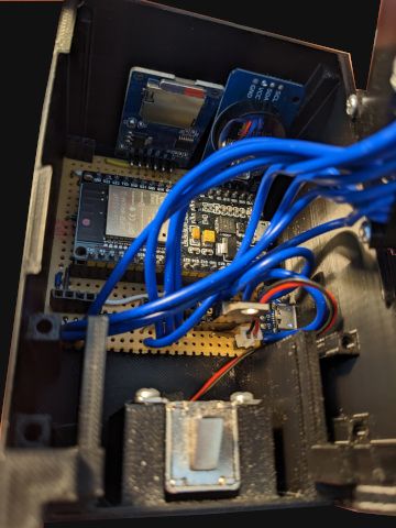
The electronics were soldered onto two stripboards, with 22-gauge wire connecting them.
The main board has the ESP32 microcontroller, Real-Time Clock, MicroSD card reader, and solenoid driver. I included an SDCard reader to store configuration data and for logging; this is something I wanted to learn how to do as it will be much more useful in future projects. The solenoid driver consists of a power MOSFET and a flyback diode.
I included a separate MicroUSB port to act as the power supply. Using the microcontroller’s MicroUSB port would limit the amount of current available to the solenoid and would also allow the lock to be bypassed by reprogramming the microcontroller. The MicroUSB module is connected to the main board using 22-gauge wire.
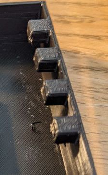
Screen #
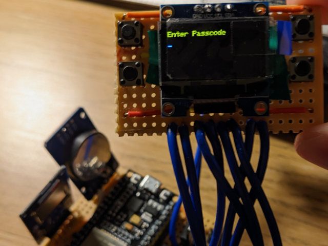
The screen board contains an SSD1306 OLED screen and four push buttons. 3D-printed button caps rest on the buttons and allow them to be pressed through the case. The lid has holes for the screens and the four button caps.
Creating the screen board was by far the hardest part of the project - space was tight and once the screen was on it blocked access to the rest of the screen board. At one point, the cheap soldering iron I was using overheated - it started glowing red hot, indicating it was over 200°C hotter than it should be! I bought a new soldering station, a Hakko FX-888D, which made soldering so much easier.
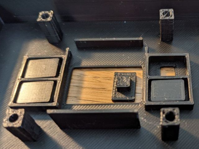
Case and lock #
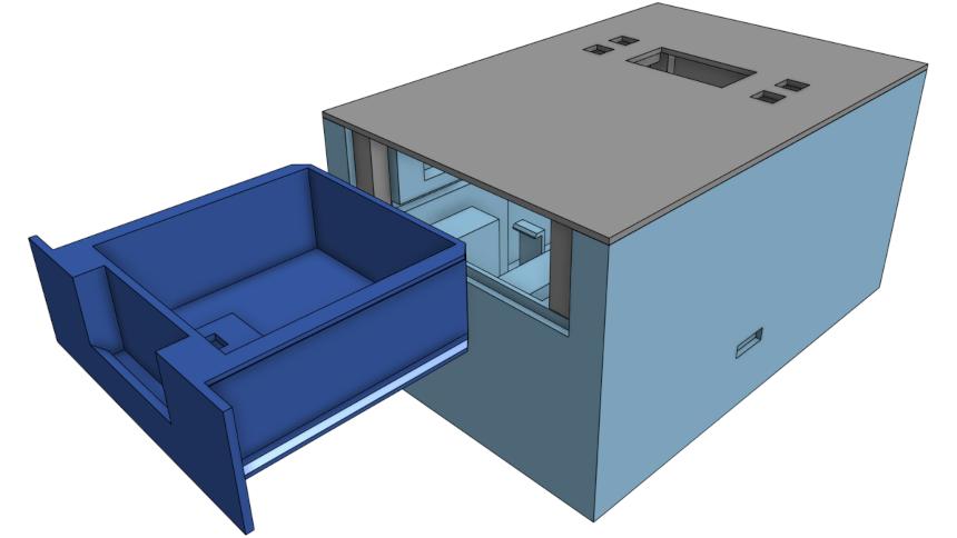
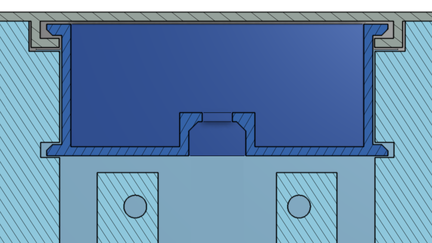
Rather than making the lid part of the lock mechanism, I added a sliding drawer to hold the contents. Using a smaller moving part prevents the issues with the plastic flexing. The drawer has a slot on the bottom for the solenoid lock, and a lip to prevent picking.
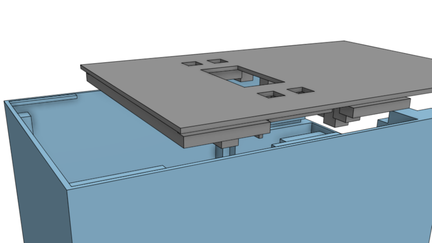
The lid slides onto the base using tabs, locking it into place vertically. The drawer slides into rails on the lid and base, locking the whole thing together. The drawer prevents the lid from sliding horizontally and provides extra strength vertically. Using the drawer to lock the lid in place is a simple and elegant way to prevent access to the electronics whilst locked - it avoids needing to use screws.
The case has a hole for the power cable and a small platform on the inside to mount the MicroUSB module using screws.
Software #
The software is pretty minimal. ESP32 uses the Arduino C++ SDK so I was able to benefit from existing libraries for components such as the display (SSD1306), Real-Time Clock, and MicroSD card reader. One of my other projects is built using the Pico C++ SDK and required me to write my own firmware for this hardware.
When connected to a WiFi network, the microcontroller will synchronise the current time using the Network Time Protocol. The time is stored in the Real-Time Clock module, allowing the time to be known whilst offline.
The user can lock the device using a pin or set up a time-based lock. The device could also use a REST API, but I didn’t get around to exploring this.
One thing that surprised me about working with the MicroSD card reader is just how slow it was. It took 0.65 seconds to open a file, write a few bytes, and then close it. Appending to a file was super fast, however, likely because the cards are optimised for sequential access. This is probably just a software problem. I used SD.h from the Arduino SDK, which uses sdfatlib, with a 32GB MicroSD card formatted to FAT32.
Future Improvements #
Increase storage space #
The drawer is too small to be useful for much - it only really fits a key or note, and not much else. This is just a prototype and a learning exercise, so it doesn’t matter that much. A larger version could have quite a few use cases, such as rewarding good habits.
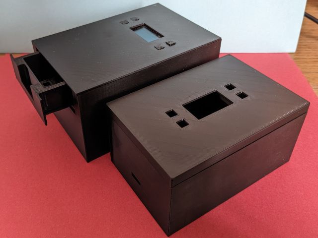
The solenoid design is 15% larger than the servo design but has 70% less storage space. Now, the old design didn’t really fit the electronics so it’s not a fair comparison, but it highlights a problem with the size of the box vs the size of the lockable storage space.
One way to solve this would be to miniaturize the electronics. A Pi Pico W would have a smaller footprint and also has a built-in RTC, so the external RTC could be removed. Making a PCB could make the electronics smaller, especially if you embed the various breakouts onto it. Glueing the screen rather than using a holder plate to screw it in would also save space.
Another option would be to make the whole thing bigger. The same amount of electronics is required, no matter the size. So making it bigger will allow the storage efficiency to be higher.
Battery #
Another possible future improvement would be to add a small li-ion battery, allowing the box to become more portable.
Limit switch #
A limit switch could be used to automatically detect when the drawer is in the box. This would be a small user-experience improvement.
Custom locks #
It would be good to get my custom mechanical designs based on servos working. Whilst there isn’t a huge amount of benefit to them, I am disappointed that I wasn’t able to get them working correctly.
Conclusion #
Well, I definitely learned a lot in this project. I probably won’t continue to work on it as I’ve already spent more time on it than I was planning and I don’t have much use for it.
I’ve been working on a new robotic car platform using a Pi Pico. The aim is for it to be a platform for me to experiment with various robotic techniques, including dead reckoning and Simultaneous Localization and Mapping (SLAM). I’d also like to learn how to use lipo batteries and RF transceivers.
Another project is likely to be an automatic watering station for my basil, which needs to be watered daily. This would be a nice continuation of my plant monitor project.
Comments