
IoT Plant Monitor using ESP32
I have a lot of houseplants, but I often forget to water them. I’ve been getting into electronics and thought this would be a great opportunity to make something.
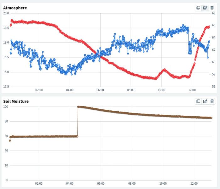
I made a plant monitor, which measures soil moisture, temperature, and humidity, and reports these things to a cloud IoT service called Thinger.io.
The Case #
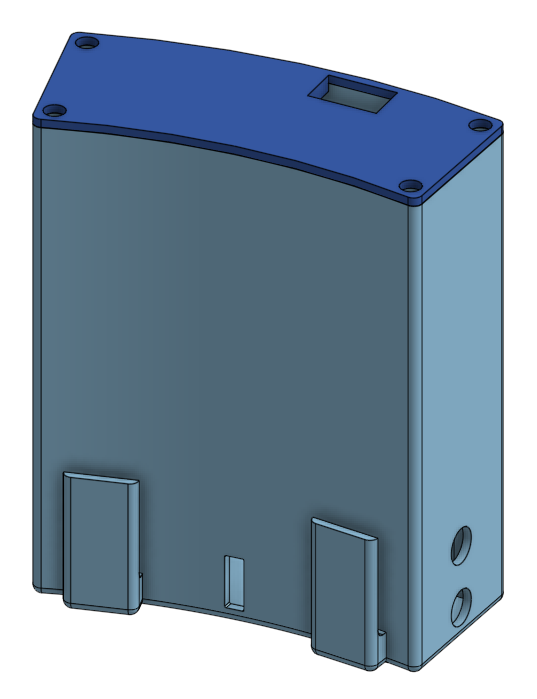
I wanted the monitor to be subtle and hidden, so I designed a case to fit between the inner planter and the outer decorative pot. I printed it using my brand new Prusa Mini+. It took many iterations to get it perfect. The electronics fit snug in the case, with ports for sensors and a microUSB charger.
The case was the first thing I made using Computer-Aided Design (CAD), and was a particularly painful task as the case is curved to fit the 23cm diameter pot.
I’ve put the files up on Thingiverse and PrusaPrinters.
Electronics #
Components #
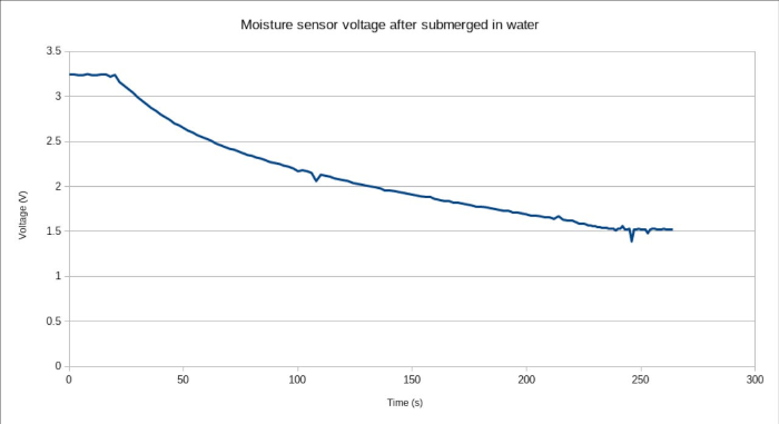
The first problem I had was finding working soil moisture sensors. I bought some capacitive soil moisture sensors from eBay, but they were very slow reacting - they took over 3 minutes to respond to changes in moisture. After some research, I found out that some low-quality sensors from China contain a capacitor in the wrong place, which smooths out the output voltage to an unusable degree. I replaced the sensors with ones bought from the Pi Hut, which worked considerably better - they respond immediately to changes in moisture. This event put me off buying from eBay for a while.
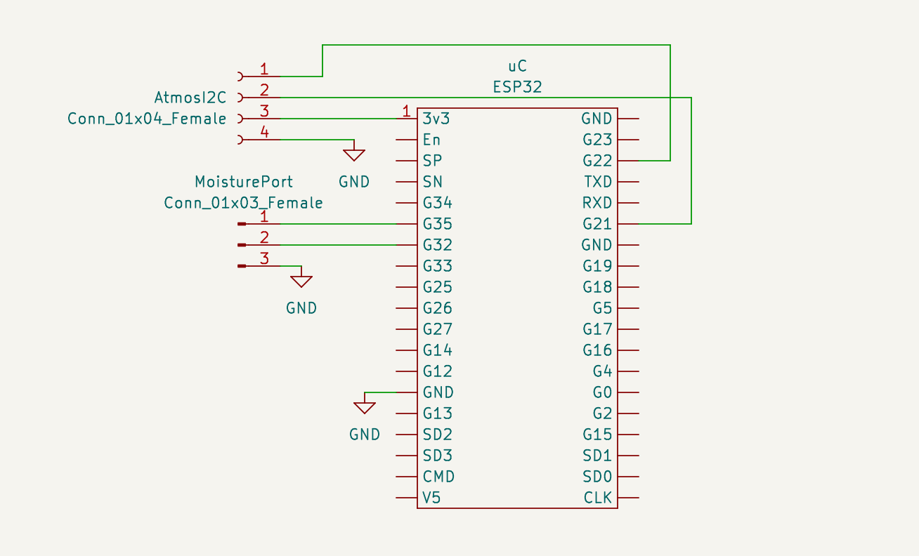
I decided to use an ESP32 as the microcontroller, as they seemed easy-to-use, abundant, and cheap. I choose a cheap ESP32-WROOM-32 devkit from a trusted eBay seller.
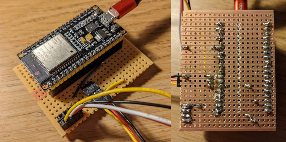
Making a permanent circuit using stripboard #
This is my first proper electronics project, and the first time I’ve made a ‘permanent’ circuit. The soldering was a bit messy but functional (I blame the flux for spitting at me, but really it’s just a lack of practice).
In order to use stripboard, you need to be able to break the copper tracks to allow the circuit to be correctly formed. I bought a Stripboard Track Cutter from the Pi Hut for this job, and it turned out to be incredibly ill-suited. It took 40 seconds of hard pressure to break a track. I’ve since bought a new track cutter from eBay that only takes a few seconds of basically no pressure, so I’ll definitely be using that for future projects.
The soil moisture sensor is a simple analog 3-pin device - two for power, one for a voltage reading. The output voltage decreases with moisture. This sensor connects to the board using a 3-pin male header.
The temperature/humidity sensor uses Inter-Integrated Circuit (I2C), a low-level serial communication bus, to communicate with the microcontroller. I2C requires 4-pins - two for power, and two for the bus.
I included connectors for two I2C devices, with space on the board for up to four devices. I only use one I2C device currently, but I’m likely to add more devices such as a light intensity (lux) sensor in the future.
I bought some 4-pin JST PH connectors for I2C, but ended up using female headers instead as JST PH’s 2mm spacing doesn’t fit the stripboard’s 3mm spacing. Perhaps in the future I’ll either make a PCB or create an adapter, allowing JST PH to be used.
Internet of Things with Thinger.IO #
I was tempted to implement my own cloud IoT platform, but then I reminded myself that the point of this project was to learn electronics and 3d printing, not to spend hours reinventing the wheel.
I did some research on existing IoT platforms, and choose Thinger.IO as it is open source and seemed to have the right balance of simplicity vs capability.
Integrating with Thinger.IO with the microcontroller was as simple as including their SDK and writing up a few lines to publish the sensor values.
Setting up the dashboard on Thinger.IO was a bit more complicated. It took a while to work out how to record data rather than just show it, I needed to use a data bucket with manually posted values, and then write to it every 5 minutes from the microcontroller. I would have preferred that the microcontroller just expose the sensor values, and not care about what the IoT platform does with it.
Source code #
The source code is pretty basic, this was definitely more of an electronics project than a programming one!
#include <Arduino.h>
#include <Adafruit_SHT31.h>


#define THINGER_SERIAL_DEBUG

#include <ThingerESP32.h>
#include "secrets.hpp"

ThingerESP32 thing(USERNAME, DEVICE_ID, DEVICE_CREDENTIAL);

#define MOIS_LOW 1.8f
#define MOIS_HIGH 2.2f


int moistureReadPin = 35;
int moistureEnPin = 32;

Adafruit_SHT31 sht31 = Adafruit_SHT31();


float measureSoil() {
    Serial.println("Measuring soil");

    digitalWrite(moistureEnPin, HIGH);
    delay(1000);

    int raw = analogRead(moistureReadPin);
    float moisture = raw * 3.3f / 4095.0f;
    digitalWrite(moistureEnPin, LOW);
    return 100.f - 100.f * (moisture - MOIS_LOW) / (MOIS_HIGH - MOIS_LOW);
}


void setup() {
    Serial.begin(9600);

    pinMode(moistureReadPin, INPUT);
    pinMode(moistureEnPin, OUTPUT);

    if (!sht31.begin(0x44)) {
        Serial.println("Couldn't find SHT31");
        while (1) {
            delay(1);
        }
    }

    sht31.heater(false);

    thing.add_wifi(SSID, SSID_PASSWORD);

    thing["data"] >> [](pson &out) {
        out["temperature"] = sht31.readTemperature();
        out["humidity"] = sht31.readHumidity();
        out["soil_moisture"] = measureSoil();
    };

    thing.handle();
    thing.write_bucket("Plants", "data");
    ESP.deepSleep(60 * 1000000);
}


void loop() {
    // Never executed due to deep sleep
}
Conclusion #
This was a very nice project to learn electronics and 3d printed, I certainly learned a lot. I still forget to water my plants, but at least I do so in a high-tech fashion!
I look forward to working on more complicated projects in the future, from electronics to mechanical design.
In the future, I’d like to add a light intensity (lux) sensor to the monitor. I need to think about where to put the sensor, as putting it on top of the pot will result in an inaccurate reading. This is due to sunlight being obstructed by the pot, and the difference in height to the leaves.
This project has seeded many ideas for future projects, such as self-watering plants, a weather station, a monitored indoor greenhouse, and hydroponics. I plan to seed basil and a few other herbs soon, having a mini indoors controlled greenhouse with grow lights could be a cool project.
Comments